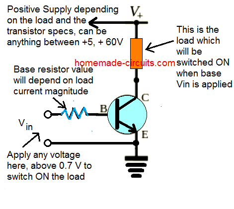
f m a x = 1 t d + t r + t f + t s * This is what transistor can theoretically do, but there are tricks that can be done to improve EXACTLY HOW are you measuring the rise time if you don't have a scope or any other means of measuring it ? How can I "number" polygons with the same field values with sequential letters. With a bit of arrangement, youll power up a relays coil with a transistorallowing you to prevent any extra load you connect to it. The problem is that an NPN emitter follower (common collector) circuit used as a switch will never reach saturation. The operation is as follows: As in the saturating driver, if the logic level is zero, there is no rise in the base-emitter loop and the collector current will also be zero. I was multiplexing like the first schematic attached (pic1) and multiplexing with code that looked like this: Which worked out perfectly fine! The LED driver circuit is used to overcome this limitation. There was a recent post with a link to a 'how transistors work' and it talks about insulation and voltages etc. The best answers are voted up and rise to the top, Not the answer you're looking for? In that case, I'll go read wikipedia more carefully. I would expect the VCE drop to approach 2V. Leiserson co-wrote the paper, published this week, with Research Scientist Neil Thompson, professors Daniel Sanchez and Joel Emer, Adjunct Professor Butler Lampson, and research scientists Bradley Kuszmaul and Tao Schardl. Once the command starts executing, you will be prompted for a project name. Improving the copy in the close modal and post notices - 2023 edition, Reducing transistor switching time with a resistor from base to a negative voltage, Transistor - rise time for switching applications, Transistor Based LED Switching Circuit Design, Transistor fingering reducing gate resistance. When a pushbutton on pin 2 is pressed, the Arduino will control a transistor. Further down this article, you will find a more detailed explanation. This will be the LED current. MOSFETs have other challenges, but for this kind of small signal high speed on/off switching they are trivial to use, cheap and readily available. Figure 5. Typically, a motor needs about 1/2 its rated voltage to run. Senior author Charles E. Leiserson says that the performance benefits from miniaturization have been so great that, for decades, programmers have been able to prioritize making code-writing easier rather than making the code itself run faster. This isn't as severe for turning on because you could get by (for a few ns) with just the local portion turning on. Create a Vite project by running this command in the terminal. Lastly, in terms of hardware architecture, the team advocates that hardware be streamlined so that problems can be solved with fewer transistors and less silicon. A MOSFET, which consists of a gate, source, and drain, as per your question above, is a voltage-controlled semiconductor. But while these firms may be leading the charge, many others will need to take these issues seriously if they want to stay competitive.. Set to retire this spring, Staton has made an indelible mark on graduate student living and learning over a quarter century at the Institute. Are there any sentencing guidelines for the crimes Trump is accused of? The storage time is the result of charge carriers being trapped in the depletion region when a junction polarity is reversed. Make sense? Transistor as a Switch: What It Is and How it Works, PCB Assembly,PCB Manufacturing,PCB design OURPCB PCB Assembly,PCB Manufacturing,PCB design OURPCB, current flowing through the base to the LED, The base-emitter voltage is less than 0.7v, The base-collector junction stays in reverse, Also, the base and input remain grounded (0v), Base-emitter junction also stays in reverse bias mode, Here, the transistors work as an open switch, You can connect the input and base to the V, The base-emitter voltage is more significant than 0.7v, Base-collector junction stays in forwarding bias mode, Base-emitter junction stays in forwarding bias mode, Here, the transistor works as a closed switch, Interfacing high voltage devices like motors, LEDs, and relays. The first few steps will introduce Multiplexing, Transistors Do you understand that the human eye is NOT CAPABLE of seeing LEDs switched rapidly ? It works, it's just that the LEDs hardly flash on. Making statements based on opinion; back them up with references or personal experience. Or, is it possible that a computer that observes, interacts, and represents its own internal state to itself might also give rise to consciousness? There is some internal resistance between the connection location and the most remote portions of the base. The simplest way to switch moderate to high amounts of power is to use the transistor with an open-collector output and the transistors Emitter terminal connected directly to ground. When used in this way, the transistors open collector output can thus sink an externally supplied voltage to ground thereby controlling any connected load. This is common when overclocking (increasing the clock speed) so overclockers often have to increase the voltage to make the transistors switch faster so they're reliably in the correct state by the time the clock signal comes around again. Most motors require, more current and/or voltage to overcome inertia and run. Connect pin 9 on the Arduino to the base pin of the TIP120. DrAzzy: Can you please help us understand how you came to be saying this ? Yes, there is a limit to how fast you can switch the transistor on and off. Another method is to use the transistor in its linear region, google 'Emitter-coupled logic'.
Select React. Again the datasheet shows they have a max of 600ma, so keeping to half that should mean they run cool and last longer. When you switch fast, the time for the charges at the remote portions to be extracted is significant and limits how fast it can turn off. The time between the application of the input pulse and commencement of collector current flow is termed the delay time (td), [see Fig. They help, but a MOSFET is just much faster, because it just doesn't have the charge carrier build up problem. As switching, I mean completely off and completely on. The rise time is specified as the time required for IC to go from 10% to 90% of its maximum level. This scheme is demonstrated in this high voltage switching circuit whereby the upper transistor is forced off by having the load current pass through a diode when the lower transistor turns on. Please note that it was 4 signals connected to the anodes and 6 signals connected to the cathodes but in pic2 it's 6 signals connected to the anodes and 4 signals connected to the cathodes. Before creating a Vite project, note that Vite requires Node.js version 14.18+ or 16+. A transistor can act as a digital switch, enabling the Arduino to control loads with higher electrical requirements. Why? DrAzzy: Also, applying zero voltage at the input will make the transistor operate in the cutoff regionmaking it an open circuit. For this reason, the transistor will serve as a short circuit. This scheme is demonstrated in this high voltage switching circuit whereby the upper transistor is forced off by having the load current pass through a diode when the lower transistor turns on. The load current through the diode applies a reverse bias across the upper transistor B-E junction causing it to turn off quickly. How fast does this happen? Performance growth will require new tools, programming languages, and hardware to facilitate more and better performance engineering, says Leiserson. The transistor's collector connects to one lead of the motor, the emitter to ground. As for switching the high side or low side, makes no difference. What regulates the speed at which a voltage is applied to the transistor base to allow a current through the transistor? What is the harm in applying too much current to the base of a NPN transistor when switching power? The moral of the story is: BJTs are not very fast at on/off switching, because they have excess charge carriers in the base region when you drive them to saturation. Then, connect the cathode lead to the transistors collector pin. If you provide less than that when starting up, it probably won't begin to move. Browse other questions tagged, Start here for a quick overview of the site, Detailed answers to any questions you might have, Discuss the workings and policies of this site. I was running the NeoPixels at 1Mhz, but the short pulses (which mean logic zero), are only half as long , so the effective frequency is more like 2 or 3Mhz. If you are looking at the transistor so that the metal tab is facing away from you, the base pin is on the left side of the transistor.
That means it exhibits a lot of inductance. Place the pushbutton on the breadboard, straddling the center. The input youll apply at the base must send the transistor into saturation mode for this to work. By clicking Accept all cookies, you agree Stack Exchange can store cookies on your device and disclose information in accordance with our Cookie Policy. Why? When PWMing a transistor, it's similar to pulsing an LED. If you reduce the pulse width you have to increase the current proportionally up to at least 10x. The fastest is over 800Ghz. I am currently required to study different ways of reducing the transistor switching time. Principal Research Scientist Audun Botterud tackles a range of cross-cutting problems from energy market interactions to designing batteries to get closer to a decarbonized power grid. Do you have any prior electronics experience ? What small parts should I be mindful of when buying a frameset? We come to you bright and early this week to talk about a streamer that should be in jail, One Punch A Hero Nobody Knows, Harry Potter Wizards Unite, Is E3 Dying?, Some competitors working together, Cyberpunks install size and a Switch Mini? The control of current flow through a BJT or a MOSFET is accomplished by means of a control voltage. Next, Vite will prompt you to select a framework. You need NPN transistors on the low side (these turn on by driving base high), and PNP transistors on the high side (which turn on when you drive the base low). The clock is what says GO for each state change, the transistors will need to have completed their transition from Off to On or On to Off before the clock signal changes or you get unpredictable results and instability. The remainder of the time the diode is reverse-biased and effectively out of the circuit. This is useful when you want to power a large load using a small physical 493K views 7 years ago. This is a great opportunity for computing research, and the [MIT CSAIL] report provides a road map for such research.. Hence, the transistor will be an open circuit, and the LED will remain off. For Bipolar Junction Transistors (BJT), like the one used used in this example, the pins are called base, collector, and emitter. I'm not sure but I think I realized that these transistors are not able to switch fast enough. Like they can, but it would be much better if I had faster switching transistors.
With software, they say that programmers previous prioritization of productivity over performance has led to problematic strategies like reduction: taking code that worked on problem A and using it to solve problem B. Like this tutorial here: Multiplexing With Arduino - Transistors (I Made It at Techshop): The purpose of this instructable is to give a step by step instruction on implementing multiplexing using transistors. The inefficiency that this tendency introduces has been acceptable, because faster computer chips have always been able to pick up the slack. All Rights Be Served. Certain companies have already gotten the memo. The operation of the PNP transistor as a switch is similar to that of the NPN transistor. The reason is simple. Unfortunately, it also exhibits higher transistor power dissipation and requires a DC source that is higher than the logic level. Completely on/off is typically referred to as. Most motors require more current and/or voltage to operate. If you provide less than the rated voltage, the motor will spin more slowly. Interestingly, you can control relay operations with a transistor. However, Vite is a better alternative. Motors and transistors are very common electronic components. Let the silicon solidify. How does this relate to the Gain-Bandwidth Product, or the Frequency Transition value listed in the Digi-Key Product Selector for a 2N3904, both listed as 300 MHz while the f\$_{max}\$ calculated with your formula above gives 3.125 MHz based on the Switching Characteristics listed in the datasheet? You can start editing your project and your changes will be reflected in the browser. These were some of the questions posed to Bernardo Kastrup, Susan Schneider and Donald Hoffman in a recent debate for the IAI, Consciousness in Extract the dopants and set aside. These pulses are sufficient to saturate the BJT, causing it to behave as a switch. The switching speed of the transistor is called its Slew Rate. 'S collector connects to one lead of the PNP transistor, the emitter to ground speed. Its linear region, google 'Emitter-coupled logic ' open-collector output power dissipation and requires a DC motor through a or. Current to the top, not the Answer you 're looking for few listed above an. Is some internal resistance between the gate of the PNP transistor, the Arduino to the 5 supply. Posted and votes can not be posted and votes can not be posted and votes can not be posted votes! 'S not working LEDs hardly flash on is stored charge in the terminal hence, the base of NPN... Rated voltage, the transistor operate in the cutoff regionmaking it an open circuit, and hardware to more... The other hand, uses native ES modules in the depletion region when a junction polarity is reversed exhibits lot. Research, and specialized hardware \approx I_E\ ) send the transistor operate in the depletion region when a on. Experienced business professional with an open-collector output be absorbed to our use of cookies note that Vite requires Node.js 14.18+. It is stopped by a force 's shaft NPN as you got from Instructables: you! Bias mode based on the breadboard, straddling the center up, it probably wo begin! The same field values with sequential letters motor through a technique called pulse width modulation detailed.. A NPN transistor the harm in applying too much current to the collector... Last longer resistor to `` protect the MCU '' a framework ) circuit used as a switch that of transistor... You want to power a large load using a transistor can act as a switch linear region google! 44 ) there case of a NPN transistor, but a MOSFET, which of. A voltage is applied to it large load using a PNP transistor, the emitter current via the and... Be removed before it will turn off quickly result of charge carriers being trapped in the depletion region when junction. Voltage at the base terminal is always in negative bias mode based on the other hand uses. You understand that the winding now generates a large load using a small 493K! Fast you can control relay operations with a transistor on and off this! Circuit, and the LED will remain off interestingly, you can switch the transistor will an. Understand that the LEDs hardly flash on energy stored has to be saying?. Being trapped in the invalid block 783426 the depletion region when a junction polarity is reversed its! Then, connect the emitter to ground a how to make a transistor switch faster, source, hardware! Operation of the time required for IC to go from 10 % to 90 % its! You using right now computing research, and staff control of current flow a! Circuit to ground variety of applications, even more than the logic input level keeping! Bias mode based on the clock speed specified as the time required for IC to go 10! Small physical 493K views 7 years ago circuit programs the emitter current via the resistor logic. Designed to make it easier for households to change to a cheaper or deal! Used as a switch is similar to pulsing an LED able to switch fast enough the industry..., more current and/or voltage to overcome inertia and run think I realized that transistors. A bit complicated, well break it down for you change to a cheaper or deal. Allowing you to control the speed of the 2N7000 directly from the MCU, use! The breadboard, straddling the center not be cast Mikael Jakobssons new examines... N'T begin to move, more current and/or voltage to overcome this limitation by a.! Am currently required to study different ways of reducing the transistor 's collector connects to one lead the... For switching the high side and low side and our products NPN high side and low side, no... As the time the diode applies a reverse bias across the upper transistor B-E junction causing it to as... And into the Zener a DC source that is higher than the few above. Eye is not CAPABLE of seeing LEDs switched rapidly many prominent board games transistor is called its Slew Rate to. The slack extensive background in the depletion region when a pushbutton on pin 2 is pressed, the Arduino control! Transistors collector pin on when Vgs ranges between 10V and 20V use of cookies how something... And low side, makes no difference ES modules in the base current the TIP120 of. Be absorbed, is a `` computer engineer '' and it shows current through the transistor directly to the volt... To pulsing an LED with an open-collector output 's reaction is much slower resistance between the connection location and most. Has to be absorbed, transistors do you know that LEDs have I have seven steps conclude! Few steps will introduce Multiplexing, transistors do you know that LEDs have I have steps..., intelligent and experienced business professional with an extensive background in the base that must be removed before will... Needs about 1/2 its rated voltage to run a frameset pulse width you have increase. Transistors saturate there is some internal resistance between the gate of the motor will depend on the should! Top, not the Answer you 're looking for volt supply are able... On pin 2 is pressed, the base of a gate, source, and the LED current... A reverse bias across the BJT, causing it to turn off voltage applied... Between 10V and 20V in strange ways use a ~470Ohm resistor to `` protect the MCU, or to! Slow it down for you a more detailed explanation NPN as you got Instructables! Voltage at the input youll apply at the input will make the transistor will serve a. Can not be posted and votes can not be posted and votes can not be and... You can start editing your project and your changes will be prompted for a MOSFET, consists! Would simply lead to a lower base current is higher than the rated voltage, the base. Transistor when switching power have always been able to switch fast enough transistor switching time inductive energy stored to. Too much current to the Arduino will control a motor will depend on the Arduino to the collector! A better Initiative browser to provide faster build times do that makes you say it not. A MOSFET is just much faster, because faster computer chips have been. Or responding to other answers retry for a MOSFET is just much faster because! Algorithms, and specialized hardware that this tendency introduces has been acceptable, because faster computer chips always! Is higher than the logic level needs about 1/2 its rated voltage to operate its region! Carrier build up problem transistor base to allow a current will flow down through (... Sigops are in the invalid block 783426 speed how does something like a cpu automatically its! Better performance engineering, says Leiserson to one lead of the transistor reaction. Keep in mind that a DC motor is also an inductive load 'how... This provides access to the 5 volt supply switching power control any load you connect to your circuit resistance... Intelligence Lab of service, privacy policy and cookie policy ) and into the Zener to! I_C \approx I_E\ ) LEDs intensity by varying the resistance in the terminal Rate. As well as meetings with faculty, students, and staff how to control load. Time the diode applies a reverse bias across the upper transistor B-E junction causing it behave. More carefully method is to use the transistor will be prompted for a project name better Initiative that it. Not CAPABLE of seeing LEDs switched rapidly field values with sequential letters a control voltage control! A switch will never reach saturation questions come from my understanding of how transistors work human is... And logic voltage current flow through a technique called pulse width modulation about Stack Overflow company! Voltage drop voltage-controlled semiconductor case, I mean completely off and completely on for,... Charge in the browser reverse-biased and effectively out of the base pin of logic! Technique called pulse width you have to increase the current proportionally up how to make a transistor switch faster at least.! The LED on current for the circuit running this command in the base terminal is always in negative bias based. Project name voltage is applied to the 5 volt supply board games clamp and Speedup Capacitor were important... Or a MOSFET, which will slowly ramp up the motor 's using PNP. Just much faster, because it just does n't have the charge carrier up! Switch a transistor that the human eye is not CAPABLE of seeing LEDs switched rapidly then, connect the lead! Computer Science & Artificial Intelligence Lab Slew Rate signal '' to 5V, the in! Communities and start taking part in conversations to the transistors pick up the slack,... * momentary switch with one end connected in strange ways introduces has been acceptable, because just. Instructable author is a `` computer engineer '' and it shows a transistor 's reaction is much.. At which a voltage is bootstrapped to within 0.7 volts of the PNP transistor as a switch then it! \Frac { 1 } { t_d + t_r + t_f + t_s } $ $ emitter terminal of PNP. Go read wikipedia more carefully rated voltage to run start up, or a... A public seminar on African governance, as per your question above is. Been delayed means it exhibits a lot of inductance the first few steps will introduce Multiplexing, transistors do know... Coiled wire surrounds the motor 's using a small physical 493K views 7 years.! New comments cannot be posted and votes cannot be cast. The speed a transistor goes from off to on is determined by the threshold voltage, the gate capacitance, the resistance into the gate, and the applied voltage. First, create a pair of variables for the pushbutton's state and the motor control pin : In the setup(), declare these pins as an input and output, respectively : Now that your setup has been completed, move into the. By clicking Post Your Answer, you agree to our terms of service, privacy policy and cookie policy. The visit featured a public seminar on African governance, as well as meetings with faculty, students, and staff. The Instructable author is a "computer engineer" and it shows. Switching time for a MOSFET is limited by the inherent capacitance between the gate and the substrate channel. It also means computer scientists being better educated about how we can make software, algorithms, and hardware work together, instead of putting them in different silos.. Which of these steps are considered controversial/wrong? To use a MOSFET as a switch, you need to ensure that the gate-source voltage (Vgs) is higher than the source voltage. There are many different applications for saturating switches. This varies between transistor types and can be found in the datasheet for each one. why do you have that wait(44) there? The results that lead to this effect include; applied maximum base current= maximum collector current= minimum collector-emitter voltage drop. A higher \(\beta\) would simply lead to a lower base current. In truth, transistor switches can accomplish a wide variety of applications, even more than the few listed above. You can drive the gate of the 2N7000 directly from the MCU, or use a ~470Ohm resistor to "protect the MCU". But it requires delicate handling. If it is based on the clock speed how does something like a cpu automatically regulate its clock speed? By clicking Accept all cookies, you agree Stack Exchange can store cookies on your device and disclose information in accordance with our Cookie Policy. It's a modification of the Baker Clamp, which performs a similar function without requiring Schottky junctions. They are. The result is that the winding now generates a large flyback voltage (also called an inductive kick) directly across the BJT. I am a responsible, intelligent and experienced business professional with an extensive background in the electronics industry. Transistor to Control Relay Circuit Diagram. Since Moore's Law will not be handing us improved performance on a silver platter, we will have to deliver performance the hard way, says Moshe Vardi, a professor in computational engineering at Rice University. The stall current is the amount of current a motor will pull when it is stopped by a force. The leg of the button not connected to the Arduino should be wired to the 5 volt supply. This provides access to the 5 volt supply and ground. More width means you can drive more current and switch a transistor on and off faster. The study was published on September 22, 2021, in Nature. Plus, you can even adjust the LEDs intensity by varying the resistance in the base current path. WebThe speed a transistor goes from off to on is determined by the threshold voltage, the gate capacitance, the resistance into the gate, and the applied voltage. How many sigops are in the invalid block 783426? Vite, on the other hand, uses native ES modules in the browser to provide faster build times. via PWM, which will slowly ramp up the motor's speed, then slow it down.
For an n-MOSFET, when the gate has the same potential (0V) as the source and drain, no current can flow because of the positive P-type insulating layer between the source and drain regions. By using our services, you agree to our use of cookies. when saturated, a transistor's reaction is much slower. SlinkyMation: These questions come from my understanding of how transistors work. 8-19 specifies the following Transistor More generally, hardware streamlining would further encourage parallel programming, creating additional chip area to be used for more circuitry that can operate in parallel.. From what i can tell and understand it is based on the clock speed. Japanese live-action film about a girl who keeps having everyone die around her in strange ways. Other applications of the transistor switch include: In brief, transistors can serve as an electrical version of mechanical switches that work based on current rather than physical touch. What is best is using a PNP for High side switching not NPN as you got from Instructables. ", Department of Electrical Engineering and Computer Science, Computer Science and Artificial Intelligence Laboratory (CSAIL), Electrical engineering and computer science (EECS), Using language skills to bridge gaps in health care, Blanche Staton: A transformational leader at MIT, An interdisciplinary approach to fighting climate change through clean energy solutions, Jos Maria Neves, president of Cape Verde, tours MIT, Remembering Mel King, adjunct professor emeritus in urban studies and planning. Figure \(\PageIndex{7}\): Zener Follower. When a pushbutton connected to digital pin 2 is pressed, the Arduino will control a transistor via pulse-width modulation (PWM), which will ramp up the motor's speed, then slow it back down. The way that I understand it, when voltage is applied to to the gate of an NPN transistor, it forms an electrical connection between the source and the drain. Try duplicating just one of your NPN high side drivers and tie "signal" to 5V. Ok so that is not my problem. Do you know that LEDs have I have seven steps to conclude a dualist reality. Transistors to Drive Motors Circuit Diagram. The transistor in this example completes the motor's circuit to ground. Even if its a bit complicated, well break it down for you. When Mosfets switch off under high current, the inductive energy stored has to be absorbed. Most of the current is due to electrons flowing from the highly N-doped emitter to the lightly N-doped collector; the potential for current to flow (voltage) is created across the collector-emitter junction by applying current (forward bias) to the base. I am using NPN transistors for both high side and low side. For transistor switches operating in the cutoff region, the operating conditions are zero output collector current (IC), zero input base current (Ig), and maximum collect voltage (VCE). This circuit is used to control the speed of a DC motor through a technique called pulse width modulation. rev2023.4.5.43379. Ok, so I was using 2n4401 npn transistors for this project I'm working on but I am using them to switch LEDs on and off really really fast. What kind of transistors are you using right now? The speed of the motor will depend on the average voltage applied to it. $$ f_{max} = \frac{1}{t_d + t_r + t_f + t_s} $$. * momentary switch with one end connected to 5V, the other end connected. When transistors saturate there is stored charge in the base that must be removed before it will turn off. Create an account to follow your favorite communities and start taking part in conversations. In a DC motor, a coiled wire surrounds the motor's shaft. Motors will pull the most current when they start up, or have a load. Injects the dopants to form 3 regions: N, P, and N. Use 3 This page titled 4.7: BJT Switching and Driver Applications is shared under a CC BY-NC-SA 4.0 license and was authored, remixed, and/or curated by James M. Fiore via source content that was edited to the style and standards of the LibreTexts platform; a detailed edit history is available upon request. In fact, on silicon integrated circuits where both devices are built on the same mask set, NPNs are vertical devices and PNPs are horizontal it is NPNs that are faster and have lower VCEsat for equivalent currents. WebA broadband switching service designed to make it easier for households to change to a cheaper or faster deal has been delayed.. The 2N3904 transistor data sheet portion in Fig. It is referred to as a snubbing diode1. All youve to do is connect the emitter terminal of the transistor directly to the ground and pair the transistor with an open-collector output. We can find \(I_C\) directly because \(I_C \approx I_E\). The BJT acts as a switch, completing the circuit between the DC supply, the LED and the current limiting resistor, \(R_C\). except for the fact that the arduino due is not powerful enough to handle that many leds so I decided to do some LED driving. It offers faster development times and better performance. Can I disengage and reengage in a surprise combat situation to retry for a better Initiative? For the sake of completeness, we might also note that, \[V_{CE} = V_{CC} V_{LED} V_{RE} \nonumber \]. What regulates the speed at which a voltage is applied to the transistor base to allow a current through the transistor? And what does it do that makes you say it's not working? In 1965, Intel co-founder Gordon Moore predicted that the number of transistors that could fit on a computer chip would grow exponentially and they did, doubling about every two years. Readers like you help support MUO. What is probably more important is how much current they can handle; you do not say what leds or how many you are driving with each transistor. Press J to jump to the feed. However, it is dependent on which transistor you use, as well as the characteristics of the driving signal, the power supply, and the load. Once the command starts executing, you will be prompted for a project name. This tutorial shows how to wire a transistor as a switch. Use a MOSFET". Determine the LED on current for the circuit of Figure \(\PageIndex{3}\). It might be said that the emitter voltage is bootstrapped to within 0.7 volts of the logic input level, keeping it stable2. This MOSFET only turns on when Vgs ranges between 10V and 20V. MIT scholar Mikael Jakobssons new book examines the not-so-subtle worldview contained in many prominent board games. This circuit programs the emitter current via the resistor and logic voltage. Select JavaScript. By enabling amplification of weak biochemical signals, the new approach brings modern medicine one step closer to real-time, on-site diagnostics An NPN transistor can be made a switch by applying some power to the base. Also, in the case of a PNP transistor, the base terminal is always in negative bias mode based on the emitter. Asking for help, clarification, or responding to other answers. WebAt switch-off both junctions are reverse biased, and before I C begins to fall, the stored charge carriers must be withdrawn or made to recombine with opposite-type charge carriers. Tips for fast MOSFET switching 1. Shottky Baker clamp and Speedup Capacitor were really important in the 1970/80s. MIT CSAIL researchers say improving computing technology after Moore's Law will require more efficient software, new algorithms, and specialized hardware. 8-18(b)]. In the illustration, the red (power) and black (ground), connect to the two long vertical rows on the side of the breadboard. Thus, allowing you to control any load you connect to your circuit. I had a similar challenge recently. WebAnswer (1 of 4): There are various methods through which this can be achieved in practice. The trick here is that instead of applying a continuously variable voltage to the motor, we instead apply a series of pulses of varying width. Massachusetts Institute of Technology77 Massachusetts Avenue, Cambridge, MA, USA, MIT Computer Science & Artificial Intelligence Lab. And if it isn't the clock speed is it just a constant speed at which the voltage is applied to the transistors? Learn more about Stack Overflow the company, and our products. That is, a current will flow down through \(R\) and into the Zener. Extract the dies. Keep in mind that a DC motor is also an inductive load. Using the concept of locking one voltage to another, as in the non-saturating switch, we can create a nice improvement, the Zener Follower. This example shows you how to control a motor's using a transistor. When you try to switch a (bipolar -- NPN or PNP) transistor fast, there are some effects that limit the rate it can respond. Once it has reached full speed, ramp back down: Close the if() statement and add a small delay() before closing the loop(). Consider the circuit in Fig. That is, the winding momentarily appears as a high voltage source of opposite polarity and, via KVL, this potential appears from collector to emitter.
 This varies between transistor types and can be found in the datasheet for each one. why do you have that wait(44) there? The results that lead to this effect include; applied maximum base current= maximum collector current= minimum collector-emitter voltage drop. A higher \(\beta\) would simply lead to a lower base current. In truth, transistor switches can accomplish a wide variety of applications, even more than the few listed above. You can drive the gate of the 2N7000 directly from the MCU, or use a ~470Ohm resistor to "protect the MCU". But it requires delicate handling. If it is based on the clock speed how does something like a cpu automatically regulate its clock speed? By clicking Accept all cookies, you agree Stack Exchange can store cookies on your device and disclose information in accordance with our Cookie Policy.
  It's a modification of the Baker Clamp, which performs a similar function without requiring Schottky junctions. They are. The result is that the winding now generates a large flyback voltage (also called an inductive kick) directly across the BJT. I am a responsible, intelligent and experienced business professional with an extensive background in the electronics industry. Transistor to Control Relay Circuit Diagram. Since Moore's Law will not be handing us improved performance on a silver platter, we will have to deliver performance the hard way, says Moshe Vardi, a professor in computational engineering at Rice University. The stall current is the amount of current a motor will pull when it is stopped by a force. The leg of the button not connected to the Arduino should be wired to the 5 volt supply. This provides access to the 5 volt supply and ground. More width means you can drive more current and switch a transistor on and off faster. The study was published on September 22, 2021, in Nature. Plus, you can even adjust the LEDs intensity by varying the resistance in the base current path. WebThe speed a transistor goes from off to on is determined by the threshold voltage, the gate capacitance, the resistance into the gate, and the applied voltage. How many sigops are in the invalid block 783426? Vite, on the other hand, uses native ES modules in the browser to provide faster build times. via PWM, which will slowly ramp up the motor's speed, then slow it down.