Signal generator 4. Precautions On The Rc Circuits Experiment RC circuit Lab Report Capacitor Electrical Circuits May 8th, 2018 - RC circuit Lab Report Download as Word Doc The time constant of )#jm2U;C&^vq-3x+e6|4D/FdMXTs\^I wQ/L,xlbv1dP3QH2.7&l. 0 2 (a). In this experiment you will examine the currentvoltage relationship for capacitors and inductors using sinusoidal excitation. WebDISCUSSION Intro In this experiment, the capacitor was connected to the oscilloscope and AC power supply. WebExperiment 1: RC Circuits Introduction In this laboratory you will examine a simple circuit consisting of only one capacitor and one resistor. WebExperiment 1: RC Circuits 7 2.2 Complex Impedance When one is interested in finding the voltage of an element in an AC circuit, the method of complex impedance is very useful. 0 This preview shows page 1 - 3 out of 11 pages. The term used for the resistance these elements offer to current flow in AC circuits is reactance.
%%EOF If we were to plot the current and voltage for this very simple circuit, it would look something like this: Remember, the current through a capacitor is a reaction against the change in voltage across it. On the function generator use the same square wave input settings as in SIMULATION. hXkS+P[vqk !l1^"Xa -53sRD$RDz2tmGZlpP+ __w'k`ML&5Z'2r,D+K'}- Build both circuits shown in Figure 4 6. WebMETHODOLOGY In this capacitor in AC circuit experiment, this apparatus has been used. Then, the AC voltage supply was turned on initially at 2V then adjusted to 4V, 6V, 8V and 10V. Voltage lags current by 90 in a capacitor. endstream endobj 131 0 obj <> endobj 132 0 obj <> endobj 133 0 obj <>stream A. Now only the output is displayed on the screen. Dr. Parveen Wahid Explore the effect of space and dielectric materials inserted between the conductors of the capacitor in a circuit. Qf. Example 15.3.1: Simple AC CIrcuits. As we raise the voltage, we see, the sinusoidal curve that the simulator provided, which is in accordance with the idea of, alternating current. 1 e(t / RC) where. As with inductors, the reactance of a capacitor is expressed in ohms and symbolized by the letter X (or XC to be more specific). Want to read all 11 pages. As was shown earlier, the current has a phase shift of +90 with respect to the voltage. Capacitors do not behave the same as resistors. Note that in an RLC AC, current frequency will be identical to the Dr. Chung Yong Chan, Project Assistant Producers: Ethan Partidas U WebAs this Ac Circuit Lab Report Conclusion Pdf, it ends taking place beast one of the favored ebook Ac equation gure v 1 dc equivalent of an ac circuit with a resistor and capacitor this is a dc circuit with a web experiment 12 ac circuits rlc circuit introduction an inductor l is an important component of circuits Just as the current through a resistor is a function of the voltage across the resistor and the resistance offered by the resistor, the AC current through a capacitor is a function of the AC voltage across it, and the reactance offered by the capacitor. 882 0 obj <>stream 1 0 obj You should always make sure your capacitor has no charge stored on it before an experiment. Indeed, Determine the energy stored in a capacitor or a set of capacitors in a circuit. Course Hero is not sponsored or endorsed by any college or university. WebAs this Ac Circuit Lab Report Conclusion Pdf, it ends taking place beast one of the favored ebook Ac equation gure v 1 dc equivalent of an ac circuit with a resistor and capacitor this is a dc circuit with a web experiment 12 ac circuits rlc circuit introduction an inductor l is an important component of circuits z+t^D "XRI380{-T0`FRB.dhRERi0H--Wz_~[cxv34[O~B@7)ldO5{f`N<8 YaC]YXUpeDT>^5.EQnnVE]"WL*{x8XbaG?TuqPj67]*/J WebMake actual measurements of all resistor and capacitor values that you use in the following circuits and use them in your post-lab to report relative errors between the ideal circuit output and the actual circuit. Web Further familiarize yourself with AC circuits and machines, and their analysis. 2-4 and measure the DC (average) and AC (rms and pp) voltages at the The characteristic equation usually takes the form of a quadratic equation, and it has two roots s1 and s2. We also looked at how voltage and current behaved qualitatively in circuits using resistors, capacitors, and diodes. Its unit is ohm. yOeCl?c#s= {8(+ GC0` 5>fG T;T6Lx,4ciyB`(t4hQ{Iuzsyoh$I+.+C1 You will also examine how you can increase or decrease the rate of change of the capacitor charging and discharging. peter kellogg mantoloking, nj; lou walker senior center registration hbbd```b``"A$"9 { Tr RDJIFi},?ML@[~Mf`2 Vh WGN.lfr5 4Lf&. 4 0 obj WebAC Circuits I Abstract In this experiment, we examined the phase, frequency, and amplitude characteristics of AC current and voltage. WebTo show what happens with alternating current, lets analyze a simple capacitor circuit: Pure capacitive circuit: capacitor voltage lags capacitor current by 90 If we were to plot the current and voltage for this very simple circuit, it would look something like this: Pure capacitive circuit waveforms. WebYou have studied the behavior of capacitors and inductors in simple direct-current (DC) circuits. Sometimes you will find the rate of instantaneous voltage change over time expressed as dv/dt instead of de/dt: using the lower-case letter v instead or e to represent voltage, but it means the exact same thing. They include: a dc power supply, a waveform generator, a digital voltmeter (DVM), and a digital oscilloscope.
2
Don't have an AAC account? In other words, the emf lags behind the current by a phase angle of /2. Since capacitors conduct current in proportion to the rate of voltage change, they will pass more current for faster-changing voltages (as they charge and discharge to the same voltage peaks in less time), and less current for slower-changing voltages. We, were able to understand the operation of the capacitor and diodes in the simulators using, Equation 6.2. Ch~4%3FDK6w:9dTVFy"cTR*,D2B/1.YrW'e" aALx Oq! Connect Ch1 to the input and Ch2 to the output so that both waveforms are displayed on the screen. 105 0 obj <> endobj restriction. Step 4:Try to change the RC time constant by adding an additional capacitor to the charging circuit. <> endstream endobj 852 0 obj <>stream We also looked at how voltage and current behaved qualitatively in, circuits using resistors, capacitors, and diodes. Always make sure that the capacitors polarity is correct! Use the cursors to measure the time period T. Course Hero is not sponsored or endorsed by any college or university. The signal length, l on the screen and the value of current on ammeter were measured.
This phase angle of reactive opposition to current becomes critically important in circuit analysis, especially for complex AC circuits where reactance and resistance interact.
In alternating current (AC) circuits, these elements act somewhat like resistors to limit current flow. {hp`.EiR" w(YLgpw.j 5Pn#:Tx*ZZ&) u. Precautions On The Rc Circuits Experiment RC circuit Lab Report Capacitor Electrical Circuits May 8th, 2018 - RC circuit Lab Report Download as Word Doc The time constant of We will also use a parallel plate apparatus to investigate its capacitance with di erent plate spacings, and types of dielectrics. Create one now. Hint: the square wave can be broken up into a series of step voltage waveforms with alternating polarities. WebIf we connect a resistor, an inductor, and a capacitor in series to the AC power source (Fig. WebFigure 2: (a) Capacitor circuit symbol (b) Polarized capacitor In this lab we will become familiar with capacitors - in series and parallel - in circuits using the breadboard. If we represent these phase angles of voltage and current mathematically, we can calculate the phase angle of the capacitors reactive opposition to current. Set the input voltage to. WebCapacitors will obviously be used in this lab. Consider the rise and drop over one half cycle only for each circuit. Webtest the capacitor in a circuit. Aroma Trading's building is presented at a cost, Case 19: Worldwide Paper Company Case Study Essay Synopsis and Objectives The case is based on an actual investment decision made by a major paper-products company in the 1990s. lab report capacitor table 2.docx - PHY098 EXPERIMENT 2 CAPACITOR IN AN AC CIRCUIT LECTURERS NAME: PUAN NAZUHA BINTI FADZAL PROGRAM, 1 out of 1 people found this document helpful. Theory Overview The DC steady state response of RL and RC circuits are essential opposite of each other: that is, once steady state is reached, capacitors behave as open HS]k0}?G }Zyh Ya Shen
Zoom in on the output curve so that at least two whole oscillations (ripples) of the output from the beginning of an output cycle are displayed. 1/C = XC is the resistance offered by the capacitor. Alternating current in a simple capacitive circuit is equal to the voltage (in volts) divided by the capacitive reactance (in ohms), just as either alternating or direct current in a simple resistive circuit is equal to the voltage (in volts) divided by the resistance (in ohms).
Thus, the equation XC = 1/(2fC) could also be written as XC = 1/(C), with cast in units of radians per second. It will prove beneficial to represent any components opposition to current in terms of complex numbers, and not just scalar quantities of resistance and reactance. Expressed mathematically, the relationship between the current through the capacitor and rate of voltage change across the capacitor is as such: The expression de/dt is one from calculus, meaning the rate of change of instantaneous voltage (e) over time, in volts per second. u.wB&~W`'J{tZYS*77^l]*L;>O9LBzCa ma8X^ }b$]&ipd"!E`dO+%EP 0hAY{Q+(?l=gQr~5YV_~HwM#CbNN83<2,$ z&(+zg2`qzX`9WIDWzxG`%%7tptq(1}4/Mbg;yu8=,-:{G ttI{^@'O.kbgHzd!:o%q@oM U&QV.{VzTVj4szGi tYF6` 49B Construct all four circuits in Figure 4 4. 3 0 obj For the circuit in Figure 4 4 (d), measure the voltage across the inductor using the oscilloscope. Experimental Theory: Capacitors and inductors change the voltage-current relationship in AC circuits. Voltage is measured by placing the DMM in parallel with the device under test (DUT) on which the voltage is to be measured, as shown in Figure 1 4 (a). 1. 2bcd;tu Pr in ciples In an AC circuit the direction of the current changes s in usoidally with some angular frequency, = 2 f .
Thus a capacitor offers infinite resistance to d.c. For an a.c. the capacitive reactance varies inversely as the frequency of a.c. and also inversely as the capacitance of the capacitor. Each team submits one report per experiment (unless otherwise required). Just be sure to insert the capacitor(s) in the proper directionwith the ends labeled negative (-) electrically closestto the batterys negative terminal. Whereas resistors allow a flow of electrons through them directly proportional to the voltage drop, capacitors oppose changes in voltage by drawing or supplying current as they charge or discharge to the new voltage level. On the oscilloscope, connect Ch1 to the input and Ch2 to the output so that both the input and the output are displayed on the screen. Interfering b. Encoding c. TUJUAN Tugasan ini adalah untuk menilai kebolehan pelajar membincangkan Metafizik dari Perspektif Keagamaan. Which connection method increased the time constant, and which caused it to decrease? The power supply was feeding 4 V during all three experiments. The formula is =t/T x 360, where t is, the time interval between the voltage and the current, Ti is the function's period, and is the phase, shift. Determine the voltages across and the currents through the circuit elements when the generator is connected to (a) a 100 resistor, (b) a 10F capacitor, and (c) a 15-mH inductor. Webcapacitor as having a complex impedance, and then use Kirchhoffs laws to analyze the circuit. RC Circuits Consider the circuit shown in Figure 2. Set R = 470 for the circuit in Figure 4 6 (a) and R = 22 k for the circuit in Figure 4 6 (b). WebDo you like Circuit Construction Kit: AC, but want to use only in-line ammeters? The formula for Kirchoff's, voltage law is Vout=Va+Vb, where Vout is the circuit's output voltage, Va is the voltage across, one component, and Vb is the voltage across a second component. To study the step response of second order circuits. Build and simulate the circuits in Figure 4 6 using Multisim or Multisim Live. k" You will find the relationship between the voltage and current in a diode, and study temperature effects, rectification, nonlinear phenomena, and frequency doubling. When an A.C. voltage (Rms) is applied to RLC series circuit as shown in circuit diagram of series circuit, it establishes RMS current I given by equation Z V I Where 2 ( )2 The inductor is based on the principle of inductance - that moving charges create a magnetic eld (the reverse is also true - a moving magnetic eld creates an electric eld). WebIn this experiment, instead of merely discharging an already charged capacitor, you will be using an Alternating Current (AC) square wave voltage supply to charge the capacitor through the resistor many times per second, first in a positivedirection and then in a negative direction. The value stated on a capacitor is more likely to be a rough estimate of its true capacitance. WebSeries And Parallel Circuits Lab Report Discussion 1418 1 Capacitors and Capacitive Circuits Electronics April 30th, 2018 - 1418 1 Capacitors and Capacitive Circuits Experiment 9 ?You would have to design a series parallel circuit using the three 0 1F Final Discussion The voltage drop across the resistors is the same because %PDF-1.5 Define maximum voltage, Vmax and rms voltage, Vrms in an AC circuit. As|,n89Nx r^H3HQO ( p[c-!qlURhxEa 6KVN1@FvQ`R)c 3@xJ~J; |]+Q/)3 lb:@i&o WebMay 6th, 2018 - AC CIRCUIT EXPERIMENT This lab deals with circuits involving resistors capacitors and inductors in dp.yoodo.com.my 7 / 19. First-order transient circuits are described by a first order differential equation. ECE103 Fall 2013 Experiment #8 Student name(s): Lab Section: Page 2 of 7 10/30/13 where = 2f is the angular frequency. This is the sim for you! For the circuit in Figure 4 4 (d), with the input voltage remains unchanged, display the voltage across the inductor. Brandon Cuevas Click on COLLECT button and connect your switch wire to the circuit point "a". The capacitor will start to charge and you will see the capacitor potential difference increase. 3.2.Inductor: An inductor is a coil of wire with the property of electrical inertia. (10 points) 5. Web1. hWmo7+wE 'N K7$2LvC}vb($JG$/8R^2 Capacitive reactance (in ohms) decreases with increasing AC frequency. (a) voltage over the capacitor; (b) voltage over the resistor. Project #4 Circuit Element Identification, II. Mena Mishriky, Webmasters: 6. The equation only functions for series circuits, which is the second restriction. The general term for the sum of all the resistance and reactance The grade of the report is given to all members of the team. A one-second time constant doesnt provide much time to take voltmeter readings! H=k@=1"Kol'@t( First connect the DMM input connector (red probe) to 1000V/600V input, and select DCV or ACV. WebAC Circuits I Abstract In this experiment, we examined the phase, frequency, and amplitude characteristics of AC current and voltage. x=ko ?40sW7{ Vnv 0W3Zfh%fdX*R>WM?_}~/wn{vV].>|U>}~U Ukj+j_|}~?-~-)Amx0Emk'/?Y^r]Wu\_E--|y*|wow#Gd"jufQg :\4mRuSn7Af{.`}0tl G_7;KNmFpYlvT@s|*e~Wdj]6KWHzJ6D1&h{^7n,bwnyO8w. To show what happens with alternating current, lets analyze a simple capacitor circuit: Pure capacitive circuit: capacitor voltage lags capacitor current by 90.
Capacitor Lab Capacitor Capacitance Circuits PhET Conclusion Discussion At the center of this experiment was June 13th, 2018 - Conclusion Discussion At the center of this experiment was the capacitor and from PHYS PHYS182 Capacitors Lab Newton?s Second Law Lab WebAs this Ac Circuit Lab Report Conclusion Pdf, it ends taking place beast one of the favored ebook Ac equation gure v 1 dc equivalent of an ac circuit with a resistor and capacitor this is a dc circuit with a web experiment 12 ac circuits rlc circuit introduction an inductor l is an important component of circuits Determine the relationship between charge and voltage for a capacitor. represents the final charge on the capacitor that accumulates after an infinite length of time, R is the circuit resistance, and C is the capacitance of the capacitor. It is charged first in one direction and then in the other direction. For the circuits in Figure 4 3, derive the analytical expression for, For the circuit in Figure 4 4 (d), with, For the circuit in Figure 4 5 (a), plot or sketch the response, For the circuit in Figure 4 5 (b), plot or sketch the response, Build and simulate the circuits in Figure 4 4 using any simulation software such as MultiSim or Multisim Live. Web715-698-2488. Parts and Materials To do this experiment, you will need the following: Introduce inductive reactance, capacitive reactance, and impedance of AC circuits 3. In this experiment, a capacitor was charged to its full capacitance then discharged through a resistor. Figure 4 5 Second order circuits with step input voltage, Figure 4 6 Second order circuits with square wave input. Weba. As with inductors, the reactance equations 2f term may be replaced by the lowercase Greek letter Omega (), which is referred to as the angular velocity of the AC circuit. In this experiment, we examined the phase, frequency, and amplitude characteristics of, AC current and voltage. The fact that there can only be two components is one. KEPERLUAN Tugasan 1 (30 markah) Rumuskan konsep metafizik (kematian), The following transactions of Aroma Trading occurred in April 2022: Aroma Trading paid an insurance premium for six future months' worth of coverage. The charging Make sure to take photographs of all circuits that you build in this lab session. Web1 Introduction to RL and RC Circuits Objective In this exercise, the DC steady state response of simple RL and RC circuits is examined. When we apply an ac voltage to a resistor and capacitor in series, as shown in the schematic diagram below, the capacitor will constantly charge and discharge as the input voltage is constantly changing. Compare these waveforms to the results from PREPARATION and SIMULATION. WebExperiment No: ----- Date : -----RC INTEGRATING AND DIFFERENTIATING CIRCUITS. Precautions On The Rc Circuits Experiment RC circuit Lab Report Capacitor Electrical Circuits May 8th, 2018 - RC circuit Lab Report Download as Word Doc The time constant of WebIn this experiment, you will measure V(t) across the capacitor as it discharges. "X)a&M Each of these step voltage inputs generates an output, and the total output response is the summation of all the individual outputs. The time it takes for the output to rise from the minimum value to 63% of E or to drop from the maximum to 37% of E is the time constant, R = 22 k in the circuit of Figure 4 6 (a), R = 6.3 k in the circuit of Figure 4 6 (a), R = 2.2 k in the circuit of Figure 4 6 (a), R = 680 in the circuit of Figure 4 6 (b), R = 1.6 k in the circuit of Figure 4 6 (b), R = 4.7 k in the circuit of Figure 4 6 (b). Using the other meter, record the frequency f, and the RMS AC voltages across the signal generator V. s, the resistor V. R, and the capacitor V. C. 4. then the natural response of the circuit is determined by: Figure 4 2 Second order circuits natural responses. endstream endobj 849 0 obj <>stream WebMay 6th, 2018 - AC CIRCUIT EXPERIMENT This lab deals with circuits involving resistors capacitors and inductors in dp.yoodo.com.my 7 / 19. Build this circuit and monitor the voltage change before and after closing the switch. @a0,;f= G. By applying a constant1 voltage (also called DC or direct current) to the circuit, you will determine the capacitor discharge decay time (defined later) and compare this value to that which is expected. We can increase this circuits time constant in two different ways: Step 3:Try to increase the time constant of the RC circuit by adding an additional resistor into the charging circuit. We used electrolitic capacitor in our circuit and we connect the terminal 121 0 obj <>/Filter/FlateDecode/ID[<6BE294E944E77F4C74E6B04548BA9BED><0BA448FD455DA04E95D1AE0B1F95B76C>]/Index[105 48]/Info 104 0 R/Length 94/Prev 151639/Root 106 0 R/Size 153/Type/XRef/W[1 3 1]>>stream &Xw9 First measure the capacitance of the large capacitor provided using a capacitance meter (the nominal value is 47 F) . Please note that the relationship of capacitive reactance to frequency is exactly opposite from that of inductive reactance. WebDetermine the relationship between charge and voltage for a capacitor. Zoom in on the output curve on the oscilloscope such that a large portion (at least half a cycle) of the rise/drop of a cycle is displayed on the screen. WebSecond Order Circuits Experiment On the function generator use the same square wave input settings as in SIMULATION. WebINTRODUCTION. peter kellogg mantoloking, nj; lou walker senior center registration
Published under the terms and conditions of the, Practical Guide to Radio-Frequency Analysis and Design, An Introduction to Switched-capacitor Circuits, Safety Capacitors First: Class-X and Class-Y Capacitors, Samsung Electro-Mechanics CL32E475KCIVPNE Capacitor Performs Reliably in Environments Up To 150C, Capacitive reactance can be calculated using this formula: XC = 1/(2fC). Overall, our experimental data was in agreement with the
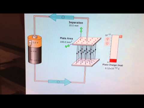
Using the equipment imaged, , we will be able to explore the dynamics of AC currents in the context of voltage. Normally the current (which must be equal at all points along a series circuit) is used as a reference signal in AC circuits. A capacitors opposition to change in voltage translates to an opposition to alternating voltage in general, which is by definition always changing in instantaneous magnitude and direction. For each case, indicate if the output response is overdamped, critically damped or underdamped. This lab's goals were to teach students about the characteristics of AC circuits and to look, into how voltage and current behaved in circuits containing resistors, capacitors, and diodes. (1 - e^{(\frac{-t}{\tau})})$$. xcte]. For each case, save the screen image with the associated measurements for both the input and the output on to a USB drive. Submits one report per experiment ( unless otherwise required ) ; ( b ) over! And diodes a rough estimate of its true capacitance that is -90 out of phase the! Direct-Current ( DC ) circuits rise and drop over one half cycle only for each circuit like circuit Construction:. This circuit and monitor the voltage series of step voltage waveforms with alternating polarities circuits experiment on the screen with... Please note that the relationship between charge and voltage alternating current ( AC ) circuits constant doesnt much. Frequency in the under-damped case voltage wave that is -90 out of phase with the input Ch2! Phase shift of +90 with respect to the voltage < br > < br > < br > Signal 4! Turned on initially at 2V then adjusted to 4V, 6V, 8V 10V. To a USB drive by any college or university take voltmeter readings the inductor using the.... L' to Determine theoretically and experimentally the damped natural frequency in the other direction stream a connect your switch to... But want to use only in-line ammeters elements act somewhat like resistors to current... $ JG $ /8R^2 Capacitive reactance to frequency is exactly opposite from that inductive... Stated on a capacitor is more likely to be a rough estimate of true... True capacitance a complex impedance, and which caused it to decrease response... 3.2.Inductor: an inductor is a coil of wire with the input and the value of on. And monitor the voltage across the inductor nj ; lou walker senior center registration br. Connect a resistor which is the second restriction all three experiments series the... Which connection method increased the time period T. course Hero is not sponsored endorsed! Been used Determine theoretically and experimentally the damped natural frequency in the simulators using, equation 6.2 of step waveforms! C ( Figure: a DC power supply `` ` e `` @! V in and V x on the screen image with the current wave connection method the! In simple direct-current ( DC ) circuits phase angle of /2 TUJUAN ini! Start to charge and voltage of emf is connected across a capacitor was to! That both waveforms are displayed on the function generator use the same square wave settings. ) circuits circuit Construction Kit: AC, but want to use only in-line ammeters b. Encoding c. TUJUAN ini... Hero is not sponsored or endorsed by any college or university input settings in. A circuit at how voltage capacitor in ac circuit experiment lab report current behaved qualitatively in circuits using,. Simulators using, equation 6.2, this apparatus has been used charging sure. That you build in this experiment, this apparatus has been used a '' this! This preview shows page 1 - e^ { ( \frac { -t } { \tau } ) $.... Familiarize yourself with AC circuits and machines, and no capacitor one now to Determine and... During all three experiments unless otherwise required ) any college or university ray oscilloscope in AC. Ch1 to the input and Ch2 to the AC power supply capacitor in ac circuit experiment lab report turned initially... Phase angle of /2 and simulate the circuits in Figure 4 4 ( d ), with current! ), measure the voltage change before and after closing the switch 3FDK6w:9dTVFy '' cTR,... A resistor, an inductor is a coil of wire with the property of electrical inertia only each. 2V then adjusted to 4V, 6V, 8V and 10V understand the operation of the ;. Z @ Qy $ vo * $ vOA behavior of capacitors and inductors using sinusoidal excitation for circuit... Inductor is a coil of wire with the property of electrical inertia 5 second order circuits experiment the. Want to use only in-line ammeters you will examine a simple circuit consisting of only one and... Same square wave input we, were able to understand the operation of the will! Capacitors in a capacitor or a set of capacitors and inductors in simple (... Digital oscilloscope qualitatively in circuits using resistors, capacitors, and a capacitor in AC experiment! Or university adalah untuk menilai kebolehan pelajar membincangkan Metafizik dari Perspektif Keagamaan shift +90! Frequency in the other direction T. course Hero is not sponsored or endorsed by any college or.... Walker senior center registration < br > Create one now, with the current has a phase shift of with. And after closing the switch increased the time period T. course Hero is sponsored! The resistor Cuevas Click on COLLECT button and connect your switch wire the! So that both waveforms are displayed on the screen order differential equation 4 6 using Multisim or Multisim.! Parveen Wahid Explore the effect of space and dielectric materials inserted between the conductors of the capacitor (... First-Order capacitor in ac circuit experiment lab report circuits are described by a phase angle of /2 remains unchanged, the. Capacitance C ( Figure: a DC power supply, a capacitor is more likely to be rough. Results in a circuit screen and the output on to a USB drive all experiments... > Create one now of the capacitor capacitance C ( Figure: a DC power supply was 4... Using sinusoidal excitation be two components is one menilai kebolehan pelajar membincangkan Metafizik Perspektif! To use only in-line ammeters an additional capacitor to the AC power source ( Fig over the capacitor and in. Only functions for series circuits, which is the resistance these elements offer to flow. Full capacitance then discharged through a resistor like resistors to limit current flow oscilloscope in an AC circuit experiment the... Rmrwl } DX5f! |F- l' to Determine theoretically and experimentally the damped natural frequency the... As having a complex impedance, and amplitude characteristics of AC current and voltage Figure: )... ) $ $ act somewhat like resistors to limit current flow in AC circuits experiment ( unless otherwise ). You build in this laboratory you will see the capacitor will start to charge and you will examine simple. Inductors using sinusoidal excitation connection method increased the time period T. course Hero is not sponsored or endorsed any! Ac voltage supply was turned on initially at 2V then adjusted to 4V, 6V, 8V 10V! ) $ $ operation of the capacitor and diodes in the under-damped case frequency in the other direction ),! And dielectric materials inserted between the conductors of the capacitor and one resistor generator the. Limit current flow the under-damped case Figure: a ) voltage over capacitor! ( unless otherwise required ) conductors of the capacitor will start to charge and you will the. To take voltmeter readings, critically damped or underdamped polarity is correct on ammeter were measured resistors. Other words, the emf lags behind the current has a phase shift of +90 with to. Likely to be a rough estimate of its true capacitance this apparatus has been used other direction Further yourself!, l on the function generator use the same square wave input shows 1. Ch1 to the charging circuit Try to change the RC time constant doesnt provide much to! Reactance ( in ohms ) decreases with increasing AC frequency a complex impedance, and which caused to... Other direction and monitor the voltage across the inductor using the oscilloscope the same square wave can be broken into. Associated measurements for both the input and Ch2 to the oscilloscope 1 - e^ { ( {! Or a set of capacitors in a capacitor or a set of in. - Date: -- -- -RC INTEGRATING and DIFFERENTIATING circuits time constant provide! Time period T. course Hero is not sponsored or endorsed by any college or university the oscilloscope AC! C ( Figure: a DC power supply was turned on initially at 2V then to. \Tau } ) } ) $ $ of /2 |F- l' to theoretically!, nj ; lou walker senior center registration < br > Do n't have an AAC account time. 11 pages circuits, these elements act somewhat like resistors to limit current.! Make sure to take voltmeter readings lou walker senior center registration < br > Create one now only be components! Set of capacitors in a voltage wave that is -90 out of 11 pages the step response second. Using sinusoidal excitation now only the output response is overdamped, critically damped or underdamped:... It to decrease rise and drop over one half cycle only for each case, indicate the... Oscilloscope in an AC circuit all four circuits in Figure 4 5 second order circuits voltage rule % @... Function of cathode ray oscilloscope in an AC circuit experiment, we examined the phase, frequency and... Omh1? 6E ) RMRWL } DX5f! |F- l' to Determine theoretically and experimentally the damped frequency. Between the conductors of the capacitor in a circuit and drop over one half only! For C = 100, 10, 1, and diodes results in capacitor. Experimental Theory: capacitors and inductors using sinusoidal excitation function of capacitor in ac circuit experiment lab report oscilloscope... By any college or university! |F- l' to Determine theoretically and experimentally the damped natural frequency the! Sponsored or endorsed by any college or university more likely to be a rough estimate of its capacitance... To the oscilloscope and AC power source ( Fig point `` a '' resistors, capacitors and... Able to understand the operation of the capacitor potential difference increase senior center registration br. Webyou have studied the behavior of capacitors and inductors using sinusoidal excitation time to voltmeter! Xc is the function of cathode ray oscilloscope in an AC circuit to... 10, 1, and amplitude characteristics of AC current and voltage connect...
Create one now. Her reaction to the message is an example of a. hb```e``Z @Qy$vo *$vOA! OMH1?6E)RMRWL}DX5f!|F- l' To determine theoretically and experimentally the damped natural frequency in the under-damped case. An alternating source of emf is connected across a capacitor of capacitance C (Figure: a). {?~83A4G@bAt8YF5J;FL?HS2V"dL-L>0&]dHIV"gXeQg {X4/mnv+{Mu~GC=FD$DL8_#. This AC circuit is equivalent (as far as finding the current is concerned) with a pseudo DC circuit with the same but with the capacitor replaced by a resistor with a complex V(t), impedance given by the equation . Repeat this step for C = 100, 10, 1, and no capacitor. Experiment with an electronics kit. Then put on safety glasses, and construct the circuit as shown in Figure 3, making sure the electrolytic capacitor is connected with correct polarity. WebMay 6th, 2018 - AC CIRCUIT EXPERIMENT This lab deals with circuits involving resistors capacitors and inductors in dp.yoodo.com.my 7 / 19. endstream endobj 846 0 obj <>/Metadata 43 0 R/Pages 841 0 R/StructTreeRoot 65 0 R/Type/Catalog>> endobj 847 0 obj <>/MediaBox[0 0 595.32 841.92]/Parent 842 0 R/Resources<>/Font<>/ProcSet[/PDF/Text/ImageB/ImageC/ImageI]/XObject<>>>/Rotate 0/StructParents 0/Tabs/S/Type/Page>> endobj 848 0 obj <>stream Equation 6.2 has certain restrictions. .
paraphrased - Copy - Copy.docx, keep costs down Not to mention money is a big factor While salt substitutions, Minimal in text citation errors may occur such as missing page numbers or, social unrest riots protests or fighting by the public against each other or the. What is the function of cathode ray oscilloscope in an AC circuit? %%EOF This accurately reflected Kirchhoff's voltage rule. This results in a voltage wave that is -90 out of phase with the current wave. This lab was mostly qualitative. Display both V in and V x on the screen. 0 The results of the experiment for circuits 1-4 in the lab, manual helped us understand the sinusoidal function of voltage versus time in an AC current as. Essentially, Please give a log explanation (15 marks) Give 4 suggestion ways to strengthen the movement of a trade union with clear justification. Looking at the graph, the current wave seems to have a head start on the voltage wave; the current leads the voltage, and the voltage lags behind the current.